FoMoCo carburetors series: C7BH-9510K, C9BH-9510A/B, 691W-9510VA/YA
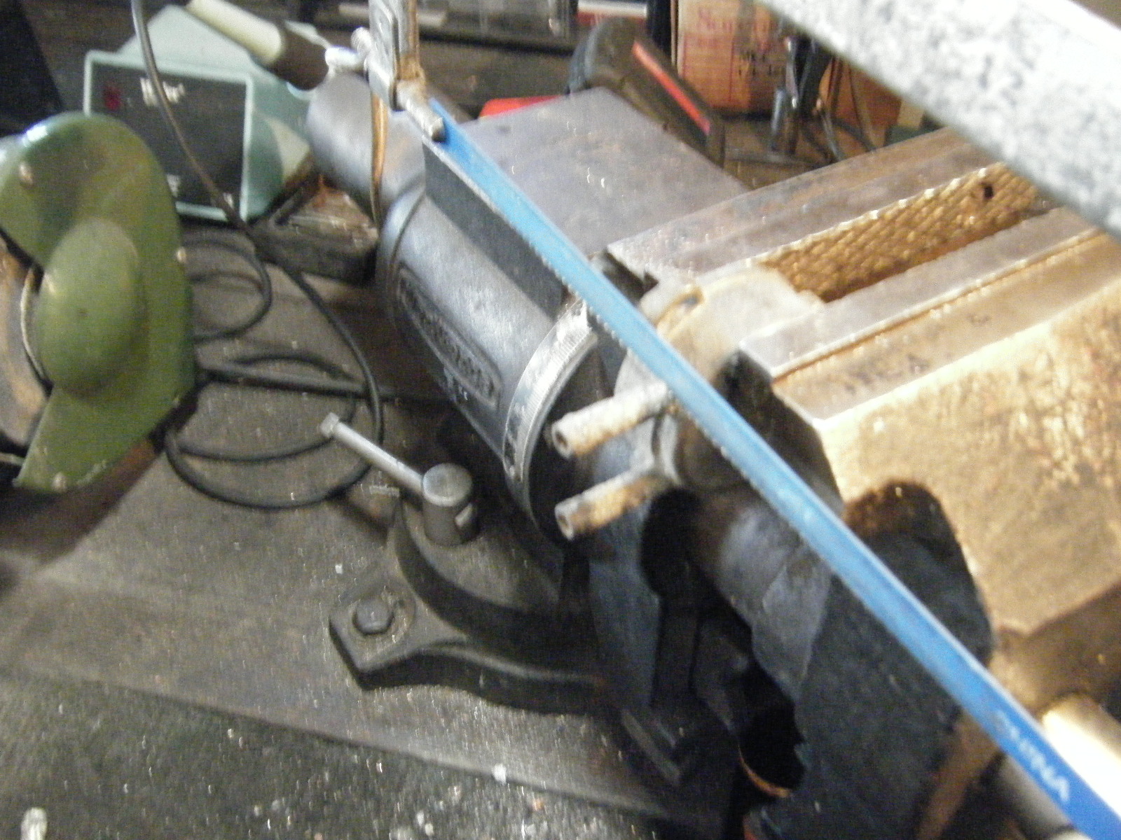
Housing water hose attachments corrode and eventually break off the housing.
Repair: Cut-off attachments. Drill a 6mm hole .5" deep into the housing then use a M7x10 tap for both holes. Cut two pieces of 1/4" OD copper tubing 1.75" long. Thread each end with a M7x10 die .5" length. ( Reason for metric sizes is that 1/4 x 24 is too small a die for 1/4" copper tubing. )
Apply epoxy on housing and copper tubing thread. Screw in water hose tubing into housing. Let set over night.
 |
| Part Number C7AH-9848A |


