Tuesday, May 24, 2016

Autolite / Motorcraft Four Cylinder Distributor Caps and Rotors

Ford officially launched Motorcraft parts division in 1972. This new brand replaced Autolite owned by Ford since 1961.
 Autolite Distributors were installed after 1966 for imported N.American Anglia 105E / 123E, Cortina MK2 '67-70 and Lotus Cortina MK2, including V4 engines.
Autolite produced two types of distributor caps and rotors for the Autolite and later Motorcraft distributors:
C7BH-12106A (1967)


C6AH-12106A (1966)


Physically the same caps except C7BH has approx. 8 degree advance rotor contact position.
I could not find any information on why Ford decided to develop this new type C7BH cap along with C6AH cap. I can only guess that the Autolite C7BH cap was produced for high revving Lotus Cortina MK2 engine in 1967 which is the correct cap and rotor C6AH-12200A for this model.


                        C6AH-12200A (1966) DORY-12200A                                 DORY-12200B


The rotor on the left is meant for the 1500 / 1600 GT engine and on the right is a larger area contact rotor meant for the 997 to 1600 standard engines.

According to parts suppliers all caps and rotors are interchangeable but the problem arises when a DORY-12200A ( GT ) rotor combines with a C7BH ( standard ) cap. The rotor doesn't align with contacts of the cap. Moving the distributor to align the contacts will alter the dwell.

In the 105E parts book lists Autolite cap as C6AH-12106A or C7KH-12106A which is the correct cap for a 997/1198 engine but the rotor listed as C6AH-12200A or C7AH-12200A is incorrect. Should have:
DOAH-12200A or DORY-12200B.

Lucas Electrical parts reference for Capri 71-73 1600 and Cortina 67-70 1600 combines RA2 rotor and DC4 cap as a set which is also incorrect. Should be DC7.

Match: Cap C7BH-12106A with Rotor DORY-12200A or DORY-12200B
Match: Cap C6AH-12106A with Rotor DORY-12200B only
No Match: Cap C6AH-12106 with Rotor DORY-12200A

Interchangeable:

Advanced Caps: Ford C7BH-12106A, Motorcraft EDH-13, Lucas DDB757 ( DC7 ),
Niehoff FF 60 E, Standard FD 146, Autolite DHE-155

Standard / Deluxe Caps:  Ford C6AH-12106A, C7AH-12106A, DORY-12106A, Motorcraft EDH-12
Lucas DDB754 ( DC4 ), Autolite DHE-156.

Short contact rotors ( GT ): Ford C6AH-12200A, C7AH-12200A, DORY-12200A, Motorcraft DRE-90,
Standard FD-113, Bremi 9563.

Long contact rotors ( Standard / Deluxe ) : Ford DOAH-12200A, DORY-12200B, Motorcraft DRE-91, Standard FD-112.


Sunday, January 3, 2016

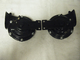
Hi / Lo Dual Horns

Cortina / Corsair / Lotus Cortina MK1 > 8/63
p/n: 113E-13800B

Non-polarity sensitive horns are isolated mounted to a bracket spot welded to the inner fender. Activated by a spring loaded switch to ground on the turn signal.

Servicing:

Decibels can be increased by turning the square head tone adjuster screw either CW or CCW. These horns are sensitive to a slight variation of voltage. If your car is equipped with a generator and the engine is idling with a load i.e lights on, there will be a voltage drop across the horns resulting low DB power.
To solve that issue, install a 20 amp relay near the horns.
Inoperative horns: Drill-out the aluminum ribbed neck rivets. Separate the two halves carefully. The diaphragm / plunger assembly and circuitry should be in good condition. Slight rusting is acceptable. Clean diaphragm and inner unit with steel wool and WD-40. Check insulation material and rivets. Clean contacts with a nail file. Remove the tone adjuster screw and check to see if the screw end did not wear through the installation thus causing the screw ground to the metal flap. If it has, glue a 1/2"x1/2"x1/16" thick fiberglass type material to the adjustment pad.

Continuity Check:

Lo Horn:  FG6 terminal #1 not grounded to housing.
                        terminal #2 not grounded to housing.
Coil check across terminal 1 and 2 approx. 120K ohms

Hi Horn:  FG9 terminal #1 not grounded to housing.
                       terminal #2 not grounded to housing.
Coil check across terminal 1 and 2 approx. 130K ohms

Testing:

Install diaphragm / plunger into coil cavity. Hold down center of diaphragm while momentarily applying 12 V to the terminals. Unit will react as a solenoid.

Assembly:

Replace paper gaskets as needed. Install diaphragm / plunger and attach horn housings. Install rivets machine screws, or such. ( I used 1/4" - 28 x 1/2" long ribbed neck carriage bolts with nuts for easy future access. You would need to increase the size of the holes to accept the ribbed neck bolts).
Install tone adjuster screw until it just touches the pad. Horn contacts are closed. Turning the tone screw CW until the contacts just open. Check this by a ohm meter probe on one terminal and the other probe
on the casing. Mounting the horns directly to the bracket without insulating and the contacts are closed will cause the horn to activate with only one hot wire to the terminal.

Testing:

Attach hot wire to the horn terminal and intermittently touch the ground wire to the other terminal while turning the tone screw CW slowly until the decibels is at max. At that point, there should be no continuity between each terminal to the base of the horn. The horns can be mounted either insulated or not.