Friday, November 2, 2012

Magnetic Drain Plugs

Magnetic engine oil drain plugs were not an option on any English Ford vehicle, to at least, up to the 1970's.
I've seen a few automatic transmissions that had a prolonged small iron magnet pressed into a drain plug but these are very weak compared to a new style magnet.

Attach a "rare earth magnet" ( Neodymium-Iron-Boron ) size: 3/8 x 1/8 to the threaded end of a drain plug by either drilling a 3/8" hole, approx. 1/8" deep for an Anglia 105E  3/4" x 24 plug type or epoxy to the end of a 1/2" x 20 plug i.e. Cortina MK2.

Once installed, this will allow you to observe any ferrous metal particles in the engine oil after an oil change.
Too much metal attached to the magnetic may indicate a problem with i.e. the camshaft lobes.

Manual transmissions have a cup-style drain plug to trap metal particles which are mostly syncro ring brass particles. By the way, the flat-end fill plug should not be installed as a drain plug.
Add a "rare earth magnet" or remove the old iron magnet on the drain plug for an Automatic Transmission.
Some of these transmissions had a iron slug magnet welded to the inner bottom of the pan which should be left in place.

Monday, October 15, 2012

Positive-Ground Systems.

The transition to negative ground came around the mid-1950's for American cars, 1967 for English Fords and around 1971 for all other English cars. The preference to use - or + ground didn't matter much. The standardization to negative ground in the Auto industry was only because of the introduction of negative ground electronic gadgets.

If you already converted the car from + to - ground, do not use the original Lucas coil marked CB and SW even though you reversed the two wires on the coil. Purchase a new coil made for negative ground systems. It should read + on one side and - on the other side of the coil.

Here's why:

Primary & Secondary Circuits on a CB / SW positive ground Coil:

When the engine is running, each time the points open, the current stops flowing and the magnetic field collapses around the primary. The secondary has approximately, 20,000 turns of fine wire ( 100 to 1 wire wound ratio secondary to primary ). The collapsing magnetic field will induce a voltage of + 22,000 volts at the core for the spark plugs.
Auto-Transformer action: In a coil the secondary and primary windings are in series.  If the wires to CB and SW were reversed then the current will flow in the opposite direction and will defeat the purpose of an auto-transformer effect. The arc-over voltage output of the coil would be approximately 10% less . It is spark current that ignites gasoline. Obviously, if you don't achieve arc-over voltage, no spark current will flow.
In other words, there is approximately 10% reduction of voltage required to jump a spark plug gap. If the car is converted to a negative ground and a negative ground coil isn't installed then the 10% voltage advantage is gone.


Tuesday, September 18, 2012

105E / 113E / 118E Transmission Back-up light Switch


 This procedure is done with the transmission removed from the car and reverse selector rod removed from the transmission. It's not necessary to completely dismantle the transmission for this step.

Anglia 105E, Classic / Capri, and Cortina MK1 models have a manual activated toggle switch located on the lower end of the shelf as standard or optional equip. After 1967 the back-up light switch were mounted on top of the transmission casing activated by the reverse selector rod.
Any early transmission casings can easily be modified to an automatic back-up light system. By using a reverse switch from the Cortina MK2 or any universal 3/8 x 24 ( 1" long shaft length ) similar switch.

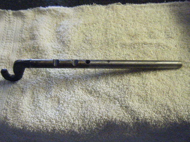
Drill a proper diameter hole directly above the reverse selector rod transmission casing, as pictured, for a 3/8" x 24 tap. Grind a 1.63" end section off the selector rod to create a 9/32" wide flat surface. Then grind a 5/16" long, approx. 20 degree slope at the end of the selector rod for a switch step-up.

Insert the rod in the casing and mount the back-up light switch. Adjust the switch so it will turn on-off ( an ohm meter will do ) while moving the reverse rod. Assemble the transmission for re-installation and mount the switch to the casing. Engage the stick shift in reverse to check activation. Leave the switch installed as it will not interfere with transmission installation.

Wednesday, September 5, 2012

English Ford Transmission Selector Forks

Worn selector forks or syncro-mesh assemblies can cause the engaged gear to jump out of its position when decelerating.
Assuming all transmission components are in good condition but the selector fork facing on both sides are worn down to 5/32" thick ( new fork facings are 1/4" thick ). This excessive play within the sleeve groove
can cause the transmission to jump out of gear.
One solution is to fill the worn area of each side of the fork by weld brazing up to 1" in length and grind smooth and form to a thickness of 1/4". Do not repair forks that are worn beyond 5/32" thickness. New forks are still available i.e., Burton Ltd.
Displayed are two 113E bronze/aluminum forks from the Cortina MK1. On the left is a worn repairable fork and on the right a reconditioned fork after weld filling and finish grinding.
I have reconditioned steel forks for Anglia 105E transmissions and brass forks for the 113E - 2000E three-rail box and later single-rail Cortina MK2 box. I found that all selector forks for these boxes have a face diameter / thickness of 1/4". Reverse selector forks don't have much wear.

Monday, August 6, 2012

Metallifacture Jacks

Metallifacture Co. ( Nowadays Magal Metallifacture Ltd ) supplied a majority of Automotive manufactures i,e., English Ford, BMC, Jaguar, Aston Martin, with Jacks and Tool kits etc. Some Jacks are identical between car manufactures.

English Ford P/N:  xxxx- 17080 series Jacks:

Consul, Zephyr / Zodiac MK1  EOA-17080C ( High Lift Square Hole Side Entry Jacks )
- Tripod Crank Jack - Square Insert

Anglia / Prefect 100E  100E-17080 ( High Lift Square Hole Side Entry Jacks )
-Tripod Crank Jack - Square Insert

Anglia 105E / Prefect 107E, Cortina MK2  105E-204E-211E-69ZB-69BB-17080 ( High Lift 7/8" Hole Side Entry Jacks )
-Tripod / Inverted HD "T" ( Crank or Ratchet Handle) Jack

Cortina / Lotus  MK1 113E-120E-17080 ( dome pin entry )
-"Y" Type Jack ( Ratchet Handle )

Defective Jack Handles can be rebuilt. The Ratchet Latch Spring may break. Remove the rivets and separate the two halves. Replace the spring with a similar type or a snail spring as used in a generator brush spring. Re-assemble using pop rivets as pictured lower handle.

Any additional Jack information would be appreciated.

Tuesday, July 3, 2012

Canister Type Oil Pressure Senders

These senders are on the Cortina GT 10/64 > 9/66. Ford p/n : C5EH-9D290B or C9EH-9D290A. 
80 psi ( stamped near the brass base ).

Function:

The oil gauge has 5 volts applied from the voltage stabilizer to one terminal the other terminal connects to the sender which acts as a variable resistor to ground.
64-66 Cortina MK1 GT Oil Sender Unit
Canister plus spring loaded plunger base cut off to expose circuitry and diaphragm

Completely disassembled unit.

As the motor is running, engine oil enters the sender and pushes against a rubber diaphragm in turn forces a spring loaded plunger to move a sweeper arm across a wire wound variable 80 - 0 ohm resistor. Oil pressure causes the 80 ohm resistor to decrease in value thus the oil gauge needle will move towards the right.
It is possible to refurbish these sender units by carefully cutting off the canister body midway around with a hack saw ( I've destroyed my sender to remove all the parts of the unit ) This will expose the internal circuitry for cleaning and damage. Oil inside the canister is an indication of a ruptured diaphram at that point the unit is unserviceable.
Carefully clean the sweeper contact, wire wound resistor and arm contact to the threaded stud. Connnect an ohm meter across the resistor, it should read approx. 80 ohms. With the ohm meter still attached across the resistor, move the plunger arm slowly so that the sweeper moves across the resistor. Resistance will decrease from 80 ohms to approx. 0 ohms without hesitation. Thus 80 ohms = 0 psi and 0 ohms = 80 psi.
Realistically the resistor should read around the 40 ohms for 40 psi. as the car is running at speed. If it works properly, the canister can be soldered back on the unit with 50/50 type solder. Don't use a torch.

Replacement senders:

Ford/Lincoln/Mercury 1960 - 80 canister senders 1/8" x 27 NPT ( for a 1/4" hole size ) approx. 80-90 psi
with a terminal button is close enough and should work.

Monday, June 4, 2012

Rotary Star Door Latches


Figure 1
Figure 2
Figure 3
The rotary star mechanisms should be in good shape before starting this project. This work can be carried out on other similar English Ford latches.
Figure 4

Figure 5
Figure 1 is a worn, early Anglia 105E door latch.
After removing the arm spring, drill out the lever arm stud rivet just enough so that the washer will come off. Remove the two levers and spring washer. Turn over the latch and file down flush the stud rivet which now can be pulled out of the latch base plate.


Figure 4.  I've removed the arm from the worn lever on the left and welded it to the fabricated lever on the right. It was easier to make a new lever from the same material and thickness and cut off the lever arm off near the base of the worn lever with a hack saw and weld it to the new lever. Take care to attach the arm at the same angle and height as the original part.


Figure 5.  I chose to install a shoulder bolt and flush nut insert ( fig. 3 ) to hold the levers in place. Added epoxy on the bolt threads and filed down the nut a bit to make it more flush. The nut should be just tight enough to allow the levers to move freely by the return spring.
Another way would be to weld the thread of the shoulder bolt to the base and then file off excess weld.
  
Oil the star rotary bushing and movement levers and grease the lever wheel. Brush a coat of grease on the whole inside latch to prevent rust. If the spring is broken replace it with a similar tension spring. Squeeze the end of the springs to prevent the spring from coming loose.


Figure 2 is a rebuilt door latch.

Disclaimer:  This information is only meant for educational purposes.