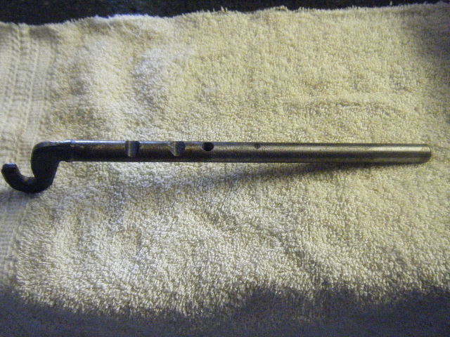
Three types of dipsticks for the Kent series front bowl oil pan. They should have the part number stamped on the end of the dipstick.
Anglia 105E/123E, Prefect 107E, Capri 109E, Cortina 1200.
P/N: 105E-6752 ( 997 / 1198 / 1340 engines )
Length: 17" to 19"
Full mark to center stop: 9.5"
Note: Error in Anglia 105E parts book: listed 105E-6752 as 105E-6752B
Cortina MK1/2 1500, Capri 116E 1500.
P/N: 105E-6752B ( 1500 pre-crossflow )
Length: 18.5"
Full mark to center stop 9"
Cortina MK2 1600.
P/N: 2737E-6752A or DORY-6750B.
Length: 20.5"
Full mark to center stop: 9.5"
Note: 105E-6752 will interchange with DORY-6750B
Timing cover
P/N: 105E-6059B EnFo and DORY-6019A FoMoCo. Interchange.
Note: Only difference is the tube boss is slightly beefier on the later FoMoCo cover.
Dipstick tube
P/N: 105E-6754 or DORY-6754A
Tube length varies: 3.5" to 4"
Tube length inserted into timing cover: 3"
Dipstick notches and tubes wear out, in some cases, nearly 1/8" worn off the dipstick notch.
Causing an inaccurate oil quantity reading on the dipstick. A way around this is to apply 3/8" thin walled shrink tube around the notch. Cut length 1" and adjust 1/4"-1/2" below the notch.
Note: Will also help seal the dipstick tube preventing blow by from a worn engine.
Showing posts with label anglia 105E. Show all posts
Thursday, June 25, 2015
Thursday, October 16, 2014
Kent Engine series Water Pumps and W/P Pulleys
Two types of water pumps (w/p) : 105E and uprated Capri / Pinto 1600.
105E type:
W/P: Ford p/n: 105E-8501A. Quinton Hazel p/n: QCP-181.
Dimensions: Hub 2 5/8". Center of Hub 3/4". Hub bolt holes 3/16". Shaft diameter: 1/2".
W/P Pulley: single groove w/o emission p/n: 105E-8509B. double groove w/emission p/n: 2737E-8509B.
Dimensions: width 4 1/4". height 1 7/16".
All U.S.A. EnFo imported models are equipped with the 105E type w/p's:
Anglia 105E, Prefect 107E, Consul / Classic / Capri 109E, Cortina MK1/2.
Cortina MK2 Master Parts Catalog lists W/P p/n: DORY-8501A and with DORY-8509B W/P pulley.
This is an uprated W/P version ( and matching pulley ) of the 105E W/P and not supplied on smog equipped models.
Uprated 1600 type:
W/P: Ford p/n: DORY-8501A. 691F-8501AA. 682F-8501A. Quiton Hazel p/n: QCP-730.
Dimensions: Hub 2 5/8". Center Hub 15/16". Hub bolt holes 5/16" Shaft diameter: 5/8". Heavy Duty Casting. On 711M block and after.
W/P Pulley: p/n: DORY-8509B
Dimensions: width 4 1/4" height 1 5/8".
Uprated W/P can be a replacement for the 105E W/P. You would need to use the matching DORY-8509B
pulley and enlarge the center hole of the fan blade to 15/16" and increase the bolt holes to 5/16".
A fan blade spacer p/n: 2730E-8A645A provided for the Cortina MK2. This part is not listed in the Cortina "C" Master Parts Catalog. The spacer should be installed on all MK2 105E type W/Ps either for metal or plastic fan blades.
All impellers should be made of metal, cast iron or steel, some after market 105E type W/P's had plastic impellers-don't use. They will come loose or melt from high heat.
105E type:
W/P: Ford p/n: 105E-8501A. Quinton Hazel p/n: QCP-181.
Dimensions: Hub 2 5/8". Center of Hub 3/4". Hub bolt holes 3/16". Shaft diameter: 1/2".
W/P Pulley: single groove w/o emission p/n: 105E-8509B. double groove w/emission p/n: 2737E-8509B.
Dimensions: width 4 1/4". height 1 7/16".
All U.S.A. EnFo imported models are equipped with the 105E type w/p's:
Anglia 105E, Prefect 107E, Consul / Classic / Capri 109E, Cortina MK1/2.
Cortina MK2 Master Parts Catalog lists W/P p/n: DORY-8501A and with DORY-8509B W/P pulley.
This is an uprated W/P version ( and matching pulley ) of the 105E W/P and not supplied on smog equipped models.
Uprated 1600 type:
W/P: Ford p/n: DORY-8501A. 691F-8501AA. 682F-8501A. Quiton Hazel p/n: QCP-730.
Dimensions: Hub 2 5/8". Center Hub 15/16". Hub bolt holes 5/16" Shaft diameter: 5/8". Heavy Duty Casting. On 711M block and after.
W/P Pulley: p/n: DORY-8509B
Dimensions: width 4 1/4" height 1 5/8".
| Left to Right: p/n 2737E-8509B, p/n 105E-8509B, p/n DORY-8509B |
| Left to Right: p/n 105E-8501A, p/n DORY-8501A |
| Water Pump Spacer p/n 2730E-8A645A |
| 105E Pump with Spacer |
Uprated W/P can be a replacement for the 105E W/P. You would need to use the matching DORY-8509B
pulley and enlarge the center hole of the fan blade to 15/16" and increase the bolt holes to 5/16".
A fan blade spacer p/n: 2730E-8A645A provided for the Cortina MK2. This part is not listed in the Cortina "C" Master Parts Catalog. The spacer should be installed on all MK2 105E type W/Ps either for metal or plastic fan blades.
All impellers should be made of metal, cast iron or steel, some after market 105E type W/P's had plastic impellers-don't use. They will come loose or melt from high heat.
Friday, May 30, 2014
204E Fuel Sender Units
EnFo p/n: 204E-9275A/B/C
For: '59-67 Anglia 105E sedan
'61-64 Consul Capri / Classic
'56-62 Zodiac / Zephyr / Consul sedan.
Unit Manufactures / Type: Float Sender Unit. Resistive wire wound Bobbin, Single Sweep.
- Smiths T.F. 1000/23 WET EnFo p/n: 204E-9275A
- AC 7228816 12V D5 EnFo p/n: 204E-9275B
Replaced by 204E-9275C. I assume that T.F. means mounted on top of fuel tank-WET, submerged.
AC/Smiths units are interchangeable.
Unit Manufacture specs: Resistive range: 12-22 Ohms to 240-290 Ohms (depending on the # of wire turns on bobbin and condition of the unit)
Wire type: Nichrome #34 .006 diameter. approx. 20 Ohms per foot non-magnetic.
Wire length: 14 ft. 200 turns.
Typical failures: Intermittent, corrosion, worn or damaged, and unit not grounded. Check that the unit is properly grounded to the body (there should be a ground wire from the sender unit mounting screw to the body/chassis) before removing the unit.
Removal: Remove unit from fuel tank. Remove the access plate from the unit (two screws or two tabs) Corroded/stuck units should be soaked in a cleaning solution ( DO NOT SAND-BLAST). Discard units with excessive corrosion on the aluminum body that has worn thru. Units in decent shape with moveable parts are more desirable. Check the float for small holes or fuel inside. Repair holes with silver solder and flux, if necessary.
Condition: Check the condition of the wire-wound resistor, sweeper contact, wire connection to the terminal. Clean the face surface of the wire-wound resistor with a cleaning solution/acid brush.
Connect a digital Ohm meter, one probe to the body of the unit the other probe to the spade connector. Move the float arm slowly from one end to the other end. A steady reading of approximately 12 ohms to approximately 290 ohms.
Corroded terminals should be removed by drilling out the rivet on the top connector side. Replace worn parts. Re-attach with a 1/8" x 5/8" long aluminum pop rivet.
Re-Winding Resistors: This procedure will require a NZ-1 winding machine. NZ-1 has been modified to accept a bobbin. It's nearly impossible to re-wind by hand. I will show you how I accomplished this.
Remove the arm/float assembly as shown (mark the position of the arm).
Remove the sweeper assembly (detach the braided copper ground strap, if there)
The bobbin is safety crimped in its guide. Carefully remove the safety tabs. Cut the wire to the terminal. Carefully remove the bobbin. You may have to move it back and forth until loose. Use WD-40 if needed. Remove the resistive wire. It may come off in sections. Total length 14'.
Alternative Resistive Wire: Kanthal A1 #34 gauge (.006 diameter ) 21.1 ohms per foot. Magnetic.
Kanthal resistive wire: chromium, aluminum, Iron.
Nichrome and Kanthal cannot be soldered with a typical soldering iron, unless excessive heat was applied. So, wrap the end of the wire a couple of times around the interior terminal. Apply electrical solder to the terminal covering the wrapped wire completely with solder.
Result: 165 turns on the bobbin and installed in the unit came to 22 ohms to 242 ohms.
I sprayed some EL601 Red Insulating Varnish on the coil but the fuel washed it off. So leaving the wire bare did not effect the resistive range. Also, I didn't attach a braided copper wire from the sweeper rod to casing ground as i figure that the cover plate notch should press against the top sweeper rod for grounding. Some units had the ground strap missing or broken in that case the unit still worked properly.
For: '59-67 Anglia 105E sedan
'61-64 Consul Capri / Classic
'56-62 Zodiac / Zephyr / Consul sedan.
Unit Manufactures / Type: Float Sender Unit. Resistive wire wound Bobbin, Single Sweep.
- Smiths T.F. 1000/23 WET EnFo p/n: 204E-9275A
- AC 7228816 12V D5 EnFo p/n: 204E-9275B
Replaced by 204E-9275C. I assume that T.F. means mounted on top of fuel tank-WET, submerged.
AC/Smiths units are interchangeable.
| Rebuilt 204E Fuel Sender Unit |
Wire type: Nichrome #34 .006 diameter. approx. 20 Ohms per foot non-magnetic.
Wire length: 14 ft. 200 turns.
Typical failures: Intermittent, corrosion, worn or damaged, and unit not grounded. Check that the unit is properly grounded to the body (there should be a ground wire from the sender unit mounting screw to the body/chassis) before removing the unit.
Removal: Remove unit from fuel tank. Remove the access plate from the unit (two screws or two tabs) Corroded/stuck units should be soaked in a cleaning solution ( DO NOT SAND-BLAST). Discard units with excessive corrosion on the aluminum body that has worn thru. Units in decent shape with moveable parts are more desirable. Check the float for small holes or fuel inside. Repair holes with silver solder and flux, if necessary.
| Corroded Unit but bobbin in good shape |
Connect a digital Ohm meter, one probe to the body of the unit the other probe to the spade connector. Move the float arm slowly from one end to the other end. A steady reading of approximately 12 ohms to approximately 290 ohms.
Corroded terminals should be removed by drilling out the rivet on the top connector side. Replace worn parts. Re-attach with a 1/8" x 5/8" long aluminum pop rivet.
Re-Winding Resistors: This procedure will require a NZ-1 winding machine. NZ-1 has been modified to accept a bobbin. It's nearly impossible to re-wind by hand. I will show you how I accomplished this.
| NZ-1 Manual Winding Setup |
| Mounted Bobbin wound with Kanthal |
| Arm removal with punch and hammer |
| Installing arm. Place arm in vise. Tap on sweeper stud. |
Remove the sweeper assembly (detach the braided copper ground strap, if there)
The bobbin is safety crimped in its guide. Carefully remove the safety tabs. Cut the wire to the terminal. Carefully remove the bobbin. You may have to move it back and forth until loose. Use WD-40 if needed. Remove the resistive wire. It may come off in sections. Total length 14'.
Alternative Resistive Wire: Kanthal A1 #34 gauge (.006 diameter ) 21.1 ohms per foot. Magnetic.
Kanthal resistive wire: chromium, aluminum, Iron.
Nichrome and Kanthal cannot be soldered with a typical soldering iron, unless excessive heat was applied. So, wrap the end of the wire a couple of times around the interior terminal. Apply electrical solder to the terminal covering the wrapped wire completely with solder.
Result: 165 turns on the bobbin and installed in the unit came to 22 ohms to 242 ohms.
I sprayed some EL601 Red Insulating Varnish on the coil but the fuel washed it off. So leaving the wire bare did not effect the resistive range. Also, I didn't attach a braided copper wire from the sweeper rod to casing ground as i figure that the cover plate notch should press against the top sweeper rod for grounding. Some units had the ground strap missing or broken in that case the unit still worked properly.
Sunday, January 6, 2013
Anglia 105E Steering Box Top Plate re-inforcement
105E steering boxes, in general, are relatively reliable units and will function properly for years as long as they are kept topped with the correct oil.
Occasionally, the steering box top plate works itself loose due to worn suspension components, unbalanced wheels, or vibration. Requiring re-tightening of the four top plate bolts. Eventually, the top plate will work loose again causing play in the steering box and steering wheel shimmy around 40 mph. A loose top plate will put stress on the internal components of the steering box.
A permanent solution to this problem would be to weld two 1/8" thick "L" brackets to the top plate and body, as shown.
Remove the top plate ( collect the spilled oil ). Produce two similar "L" shaped brackets. Mount them symmetrically together, clamp, and drill two holes for two 1/4" size head bolts and nuts. Install and tighten. Weld one bracket to the top plate, as shown in the picture. Re-install the top plate to the s/box. Tighten the four top plate bolts. Tap weld the bracket to the body. Remove the 1/4" bolts from the brackets. Remove the top plate. Cover the exposed steering box with a rag and weld the bracket to the body. Apply a bit of Locktite to the top plate bolts threads and install the bolt locking plates if desired but now, not necessary anymore.
This modification especially benefits Anglias still using a steering box for rallying.
Occasionally, the steering box top plate works itself loose due to worn suspension components, unbalanced wheels, or vibration. Requiring re-tightening of the four top plate bolts. Eventually, the top plate will work loose again causing play in the steering box and steering wheel shimmy around 40 mph. A loose top plate will put stress on the internal components of the steering box.
A permanent solution to this problem would be to weld two 1/8" thick "L" brackets to the top plate and body, as shown.
Remove the top plate ( collect the spilled oil ). Produce two similar "L" shaped brackets. Mount them symmetrically together, clamp, and drill two holes for two 1/4" size head bolts and nuts. Install and tighten. Weld one bracket to the top plate, as shown in the picture. Re-install the top plate to the s/box. Tighten the four top plate bolts. Tap weld the bracket to the body. Remove the 1/4" bolts from the brackets. Remove the top plate. Cover the exposed steering box with a rag and weld the bracket to the body. Apply a bit of Locktite to the top plate bolts threads and install the bolt locking plates if desired but now, not necessary anymore.
This modification especially benefits Anglias still using a steering box for rallying.
Friday, November 2, 2012
Magnetic Drain Plugs
Magnetic engine oil drain plugs were not an option on any English Ford vehicle, to at least, up to the 1970's.
I've seen a few automatic transmissions that had a prolonged small iron magnet pressed into a drain plug but these are very weak compared to a new style magnet.
Attach a "rare earth magnet" ( Neodymium-Iron-Boron ) size: 3/8 x 1/8 to the threaded end of a drain plug by either drilling a 3/8" hole, approx. 1/8" deep for an Anglia 105E 3/4" x 24 plug type or epoxy to the end of a 1/2" x 20 plug i.e. Cortina MK2.
Once installed, this will allow you to observe any ferrous metal particles in the engine oil after an oil change.
Too much metal attached to the magnetic may indicate a problem with i.e. the camshaft lobes.
Manual transmissions have a cup-style drain plug to trap metal particles which are mostly syncro ring brass particles. By the way, the flat-end fill plug should not be installed as a drain plug.
Add a "rare earth magnet" or remove the old iron magnet on the drain plug for an Automatic Transmission.
Some of these transmissions had a iron slug magnet welded to the inner bottom of the pan which should be left in place.
I've seen a few automatic transmissions that had a prolonged small iron magnet pressed into a drain plug but these are very weak compared to a new style magnet.
Attach a "rare earth magnet" ( Neodymium-Iron-Boron ) size: 3/8 x 1/8 to the threaded end of a drain plug by either drilling a 3/8" hole, approx. 1/8" deep for an Anglia 105E 3/4" x 24 plug type or epoxy to the end of a 1/2" x 20 plug i.e. Cortina MK2.
Once installed, this will allow you to observe any ferrous metal particles in the engine oil after an oil change.
Too much metal attached to the magnetic may indicate a problem with i.e. the camshaft lobes.
Manual transmissions have a cup-style drain plug to trap metal particles which are mostly syncro ring brass particles. By the way, the flat-end fill plug should not be installed as a drain plug.
Add a "rare earth magnet" or remove the old iron magnet on the drain plug for an Automatic Transmission.
Some of these transmissions had a iron slug magnet welded to the inner bottom of the pan which should be left in place.
Tuesday, September 18, 2012
105E / 113E / 118E Transmission Back-up light Switch
This procedure is done with the transmission removed from the car and reverse selector rod removed from the transmission. It's not necessary to completely dismantle the transmission for this step.
Anglia 105E, Classic / Capri, and Cortina MK1 models have a manual activated toggle switch located on the lower end of the shelf as standard or optional equip. After 1967 the back-up light switch were mounted on top of the transmission casing activated by the reverse selector rod.
Any early transmission casings can easily be modified to an automatic back-up light system. By using a reverse switch from the Cortina MK2 or any universal 3/8 x 24 ( 1" long shaft length ) similar switch.
Drill a proper diameter hole directly above the reverse selector rod transmission casing, as pictured, for a 3/8" x 24 tap. Grind a 1.63" end section off the selector rod to create a 9/32" wide flat surface. Then grind a 5/16" long, approx. 20 degree slope at the end of the selector rod for a switch step-up.
Insert the rod in the casing and mount the back-up light switch. Adjust the switch so it will turn on-off ( an ohm meter will do ) while moving the reverse rod. Assemble the transmission for re-installation and mount the switch to the casing. Engage the stick shift in reverse to check activation. Leave the switch installed as it will not interfere with transmission installation.
Wednesday, September 5, 2012
English Ford Transmission Selector Forks
Worn selector forks or syncro-mesh assemblies can cause the engaged gear to jump out of its position when decelerating.
Assuming all transmission components are in good condition but the selector fork facing on both sides are worn down to 5/32" thick ( new fork facings are 1/4" thick ). This excessive play within the sleeve groove
can cause the transmission to jump out of gear.
One solution is to fill the worn area of each side of the fork by weld brazing up to 1" in length and grind smooth and form to a thickness of 1/4". Do not repair forks that are worn beyond 5/32" thickness. New forks are still available i.e., Burton Ltd.
Displayed are two 113E bronze/aluminum forks from the Cortina MK1. On the left is a worn repairable fork and on the right a reconditioned fork after weld filling and finish grinding.
I have reconditioned steel forks for Anglia 105E transmissions and brass forks for the 113E - 2000E three-rail box and later single-rail Cortina MK2 box. I found that all selector forks for these boxes have a face diameter / thickness of 1/4". Reverse selector forks don't have much wear.
Assuming all transmission components are in good condition but the selector fork facing on both sides are worn down to 5/32" thick ( new fork facings are 1/4" thick ). This excessive play within the sleeve groove
can cause the transmission to jump out of gear.
One solution is to fill the worn area of each side of the fork by weld brazing up to 1" in length and grind smooth and form to a thickness of 1/4". Do not repair forks that are worn beyond 5/32" thickness. New forks are still available i.e., Burton Ltd.
Displayed are two 113E bronze/aluminum forks from the Cortina MK1. On the left is a worn repairable fork and on the right a reconditioned fork after weld filling and finish grinding.
I have reconditioned steel forks for Anglia 105E transmissions and brass forks for the 113E - 2000E three-rail box and later single-rail Cortina MK2 box. I found that all selector forks for these boxes have a face diameter / thickness of 1/4". Reverse selector forks don't have much wear.
Subscribe to:
Posts (Atom)